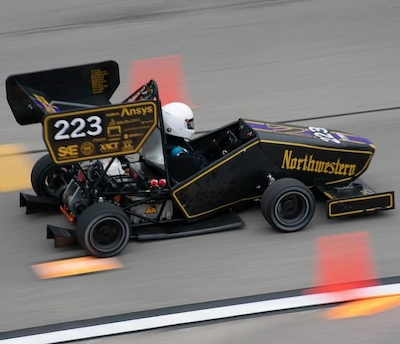
Formula SAE Rear Uprights
As a member of the Formula SAE team, I was responsible for designing and manufacturing the rear uprights for the car. My primary goal was to simplify the previous year's over-engineered design to reduce manufacturing complexity while aiming to minimize weight and including attachment points for all other suspension components.
Skills Strengthened:
- CAD Modeling (SolidWorks)
- FEA-Driven Design Optimization (SolidWorks)
- Advanced CNC Tool Path Programming (Fusion 360)
- CNC Milling
- System Integration & Multi-Constraint Design
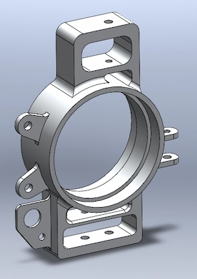
Modeling
The upright serves as the critical anchor for the control arms, brake caliper, and axle. I used SolidWorks for modeling, beginning with defining the global attachment points for the components listed above, and then building outward from bearing bore to control arm flanges. A key challenge was designing the flanges to be thick enough to support racing forces, while still allowing for full movement of the control arms and fitting within the wheel's envelope.
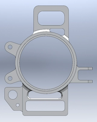

Analysis
I performed extensive FEA to validate the design and meet our required safety factor of 1.5. The axial and radial bearing loads, along with the axial forces in the control arms, were calculated for accelerating, braking, and cornering, and then input into the analysis through applied loads and boundary conditions. To the left is a plot of the von Mises stress in the part during outside cornering, the most intense scenario for the upright. The color scale is adjusted to highlight stress concentrations (red areas) which remain well below the material's yield strength, ensuring our factor of safety.
Fabrication
After optimizing the geometry, I used Fusion 360 CAM to program the CNC tool paths and machined the final component on a 3-axis CNC mill to achieve a lightweight, race-ready part.
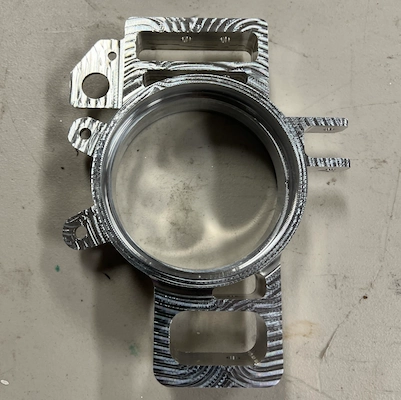
Physical Machined Upright